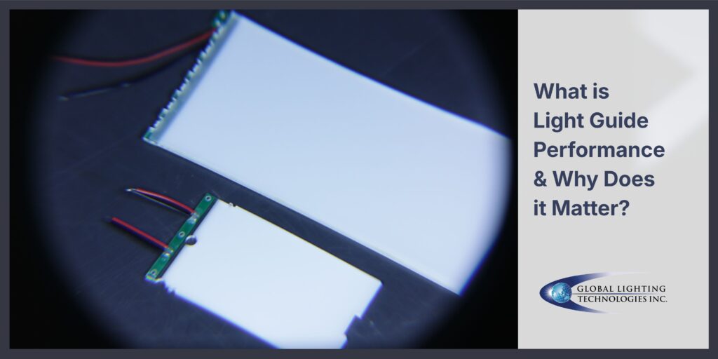
A light guide design that’s not properly tested and validated is a liability. That’s because a lot can happen between design and manufacturing, making light guide validation an essential proving ground. Below, we’ll cover what light guide validation is, what it looks like in practice, and why it matters.
At Global Lighting Technologies, we define light guide validation as the structured process that balances internal engineering standards with your application needs. In plain English, it means we have a proven process to make sure your light guide design actually functions as intended!
A strong light guide validation plan helps ensure brightness, uniformity, color, and fit-for-use performance are evaluated under realistic conditions. Our approach combines controlled measurement, customer-specific requirements, and iterative development to reduce risk before production. Read on to learn about the five major stages of our light guide validation process.
Step 1. Define the Validation Criteria
Before any measurement happens, the most important work is deciding what we’re actually measuring against. We establish key optical metrics up front. These three are the baseline for almost every project we take on:
- Average brightness (in nits)
- Uniformity (%)
- Color targets defined by chromaticity coordinates.
Of course, what counts as “passing” isn’t universal. Requirements can shift depending on the industry, end product, and how your team measures performance. Some customers come in with a full specification sheet. Others arrive with observations and goals but no formal acceptance criteria yet.
In either case, our job is to make sure internal standards and your expectations are documented in the same workflow before a single prototype is built.
Even if you don’t have defined criteria, it doesn’t stop us from moving forward. We proceed with designing the light guide assembly in parallel while working with you to define your specifications. We ask for as much information as possible and use that to begin shaping the design. If needed, we’ll set the standards by qualifying and quantifying your goals (whether observation-based or not) for consistent production quality down the line.
While every GLT project is custom—because each design and outcome is unique—the underlying process isn’t, which is a huge benefit to OEMs. We follow a well-documented process for each project that defines your specifications and design constraints, supported by project checklist templates that track progress and action items throughout.
Step 2. Assemble the Right Test Setup
Good data starts with a good test setup. Whenever possible, we use your real components because surrounding parts directly affect optical behavior, and testing with substitute materials introduces risk. The most critical components are those that directly face or interact with the light guide module. Any material the light passes through before an observer sees it needs to be accounted for early on.
If we’re not providing the PCBA or FPCA, we generally require our customers to send us the ones they plan to use so we can collect accurate data. When key components aren’t available yet, we create interim substitutes that are similar in material property and size. This provides a meaningful baseline for how the assembly will perform. We’re also transparent about the tradeoffs: we establish those risks with you up front so your team understands the likely difference between interim and final design performance.
On the fixturing side, we build custom prototypes in-house using CNC machining, 3D printers, lasers, and other workshop equipment. Once the prototype or production design is finalized, fixtures are created in parallel for both assembly and optical testing. This means the part is held in the same position for every single measurement. For more complex designs, we may work with trusted external vendors, but the goal is always the same: a controlled, repeatable test environment that minimizes variables.
Step 3. Measure Performance in Controlled Conditions
With a solid test setup in place, it’s time to measure. We conduct optical measurements in a dark room or similarly controlled environment to minimize ambient light interference and improve accuracy. Visual inspection alone won’t cut it, so we rely on precision instruments to capture results that can be compared directly against agreed-upon specifications.
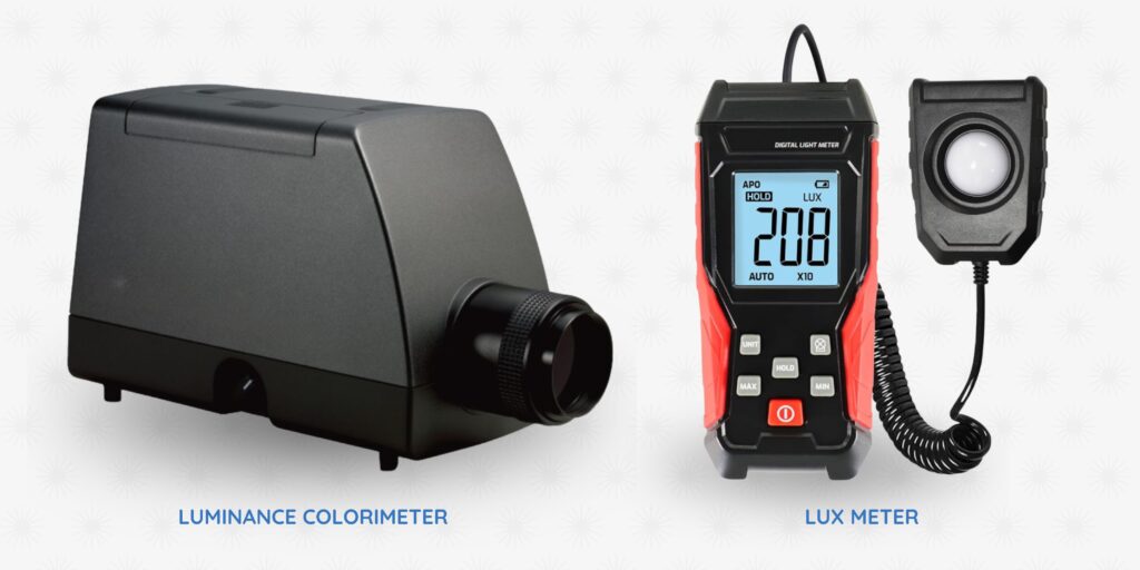
Our two most commonly used instruments are a luminance colorimeter, which measures brightness (nits), uniformity (%), and chromaticity, and a lux meter, which measures illuminance. Together, they give us a comprehensive picture of optical performance.
Repeatability is just as important as accuracy. That’s why we develop a standard Part Specification Inspection Point (PSIP) document for each program, which defines a specific set of measurement locations used consistently across all tests. Combined with our custom fixtures, which hold the part in exactly the same position every time, this ensures our results are reproducible regardless of who’s running the measurement or when. We also routinely share golden samples between facilities to cross-check that measurements are producing consistent results across different locations.
To minimize measurement error, all equipment is calibrated annually. Beyond that, alignment is one of the most common sources of variation. Even a small misalignment in the camera position, LED power source, or fixture can produce dramatically different results. Every element in the measurement chain must be controlled and repeated consistently. That discipline is what makes the data meaningful.
Step 4. Iterate Using Simulation and Prototyping
It’s important to remember that validation is a loop, not something that happens just once. Simulation is how we make that loop efficient. We bring optical simulation into the process early, while the design is still taking shape. At that stage, simulation helps us evaluate LED positioning, LED count, film selection, and uniformity, giving us confidence that the design direction is optimized before we commit to physical prototyping.
Simulations aren’t a perfect substitute for a physical part, but they’re a powerful tool for narrowing down the design space. Once real-world prototypes are built and measured, we compare those results back to the simulation. From there, we can make design changes, run updated simulations, and use the percent difference to estimate how an altered part would perform before building the next round. Over time, real-world data refines the simulation model itself, making future approximations even more accurate.
When it comes to improving uniformity specifically, our custom optical pattern design is typically the most impactful tool. They allow us to extract light across a surface and refine it to eliminate bright spots and dark spots. A diffuser can also be added to the assembly to further improve uniformity. But no optical pattern can compensate for poor LED positioning. That’s why we assess the full design holistically and account for mechanical constraints, LED count, LED placement, and material choices together in simulation before any design changes are committed to hardware.
Step 5. Finalize Customer Sign-Off
The final stage of validation is making sure you have everything you need to confidently approve the design. We present results in a format that clearly shows whether the part meets the agreed requirements and explain the context behind the data.
A typical validation package from our team includes an optical measurement document that contains:
- Performance data
- Illuminated images of the part
- Heat maps
- Measurement equipment parameters.
Depending on where we are in the program, we’ll also provide DFM (Design for Manufacturability) documentation, noting any design issues, a mold report on the light guide and other molded components, an optical report with measurement data, and SPC (statistical process control) data. You’ll also receive the 2D engineering drawings, 3D models, and dimensional report data, plus the physical prototypes so you can test fit and optical performance within your own final module.
“Sign-off” can mean different things at different stages. Early sign-off may be approval to kick off tooling based on the quotation, DFM, and projected performance. Final sign-off typically means the tooled design has been measured with real parts and is being approved for official production. Both carry different levels of data requirements and we make sure you’re clear about which stage you’re signing off on and what that means.
When results land close to the acceptance threshold, we conduct additional optical iterations on the pattern design to push performance past the threshold. In cases where the requirements themselves may be too tight, we work with you to understand what compromises are possible. These situations are rare because the goal is always to identify potential issues through rigorous review before a borderline result shows up in the data. When it does happen, though, the path forward is always a collaborative one.
Light Guide Validation Gets Things Right the First Time
Light guide validation works best when internal standards and customer-specific requirements are defined together from the start. Reliable results depend on realistic test assemblies, controlled measurement conditions, and clear performance criteria. A strong validation process like ours reduces design risk and creates a clearer, more confident path from prototype to production.
Reach out to our team to learn more about how we approach light guide validation for your application. Share your project details here and we’ll be in touch.